
OpenFOAM
- 2021/03/16
All tutorials pertaining to adjointOptimisationFoam can be found under here
$FOAM_TUTORIALS/incompressible/adjointOptimisationFoam
I. adjoint Definition
adjointRASModel found in "constant" directory to asigne adjoint turbulence model in our calculation, we can use adjointLaminar or adjointSpalartAllmaras. In this tutorial, we use adjointLaminar.
optimisationDict is the main dictionary in which almost all information about the solution of the primal and adjoint equation is set up.
- optimisationManager entry defines the mode of operation of the adjointOptimisation executable. There is two option in optimisationManager: singleRun, steadyOptimisation
- singleRun is to check whether the setup is fine or not.
- steadyOptimisation is used to calculate the optimization loop.
primalSolvers: use to define primary equation.
adjointManagers
{
am1
{
primalSolver p1;
adjointSolvers
{
as1
{
// choose adjoint solver
//----------------------
active true;
type incompressible;
solver adjointSimple;
useSolverNameForFields true;
// manage objectives
//------------------
objectives
{
type incompressible;
objectiveNames
{
lift
{
weight 1.;
type force;
patches (pressure suction);
// direction (0.034899496703 -0.9993908270189999 0);
// direction (0 0 0);
direction (0.034899496703 0.9993908270189999 0);
Aref 2.;
rhoInf 1.225;
UInf 1;
}
}
}
// ATC treatment
//--------------
ATCModel
{
ATCModel standard;
}
// solution control
//------------------
solutionControls
{
nIters 3000;
residualControl
{
"pa.*" 1.e-7;
"Ua.*" 1.e-7;
}
}
}
vol
{
// choose adjoint solver
//----------------------
active true;
type incompressible;
solver adjointSimple;
useSolverNameForFields true;
isConstraint true;
// manage objectives
//------------------
objectives
{
type incompressible;
objectiveNames
{
vol
{
weight 1;
type partialVolume;
patches (pressure suction);
}
}
}
// ATC treatment
//--------------
ATCModel
{
ATCModel standard;
}
// solution control
//------------------
solutionControls
{
nIters 3000;
residualControl
{
"pa.*" 1.e-7;
"Ua.*" 1.e-7;
}
}
}
}
}
}
II. NACA 0012 optimisation
Control points definition
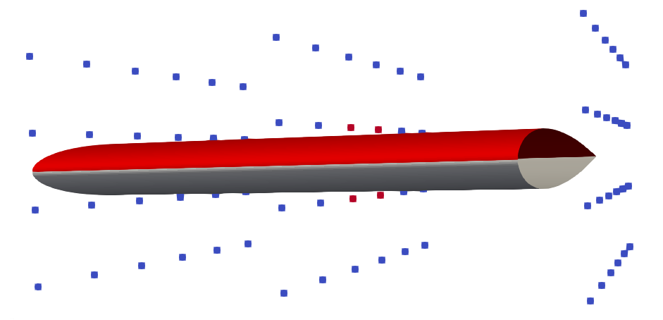
Figure a: control points consisting 6x3x3 time 0 around NACA0012.
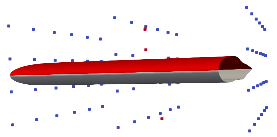
Figure b: control points definition at time 5
Control points are coloured based their j index value. Surface and volume mesh points residing withing the boundaries of the control grid will be displaced following a possible displacement of the control points
Lift Optimization for NACA 0012
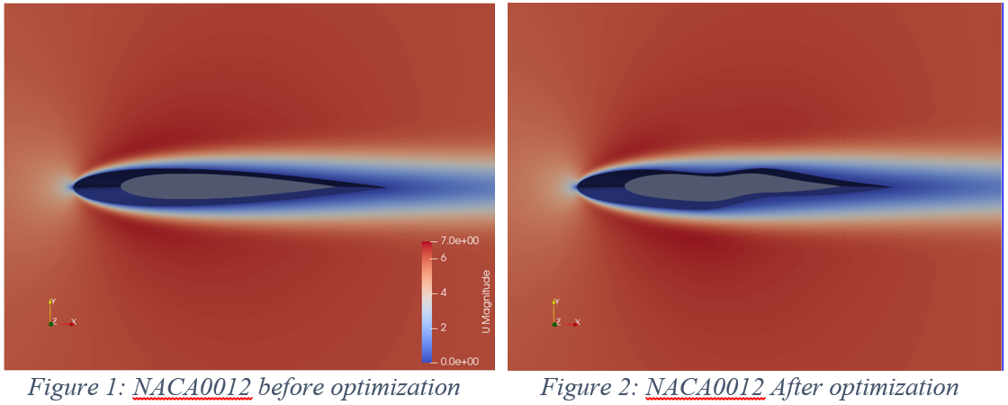
The shape of airfoil in figure 2 is weird, but we do not need to be panic, because it is normal while doing optimization.
• Lift increased by ~32%
• Drag increased by ~1.7%
• Volume is significantly distorted.
• Weird shape.
Remember! The parameterization greatly affects the optimised shape.
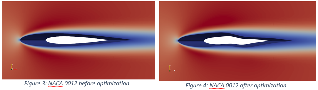
- Lift increased by 6%
- Drag increased by 0.9%
- Volume is less distorted than the previous case